This DIY describes how to remove the valve cover on a 2007 CBF1000A Honda motorcycle and is applicable for 2006 to 2009 models. This is typically done as part of a valve clearance inspection.
This is not an easy DIY task. It involves quite many individual steps, some of which are a bit triggy and which - if not done with care - may damage components. Especially the high tension spark plug leads, coils and caps are prone to be damaged if handled too hard. A first timer may spend 12 hours or more doing it, an experienced might do it in 4 hours. If you are a beginner in DIY, better have an experienced friend giving a hand.
Tools, spareparts and consumables needed:
1.0 Remove seats - details
2.0 Remove upper cowls and inner pannels both sides - details
3.0 Remove lower cowls both sides (if mounted) - details
Remark: The Honda Shop Manual specifies removal of the tank at this point, but it is simpler to just lift it as specified in the following step.
4.0 Lift the tank - details
5.0 Drain the coolant - details
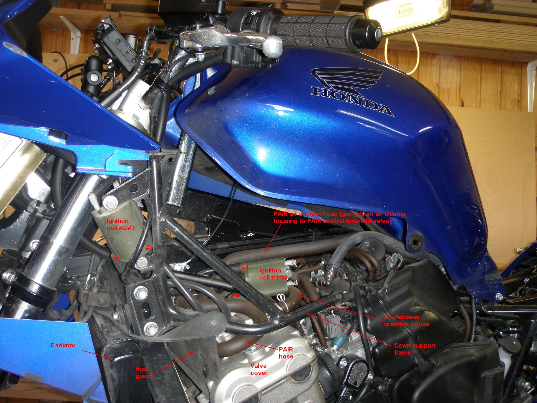
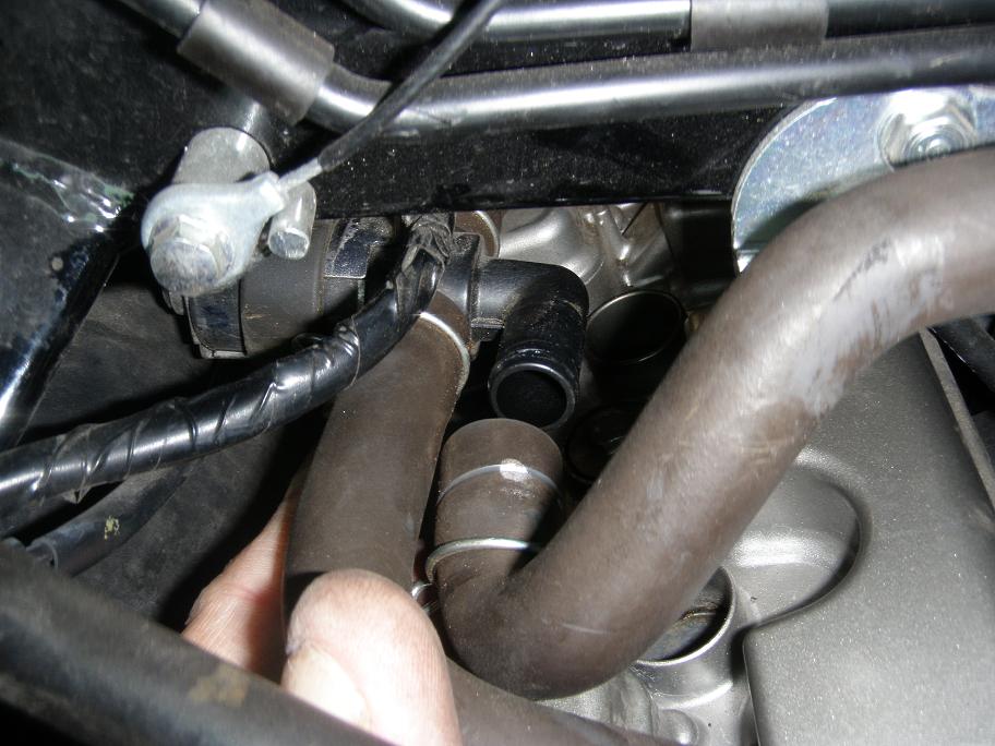
6.0 Ignition coils, high tension cables and spark plug caps.
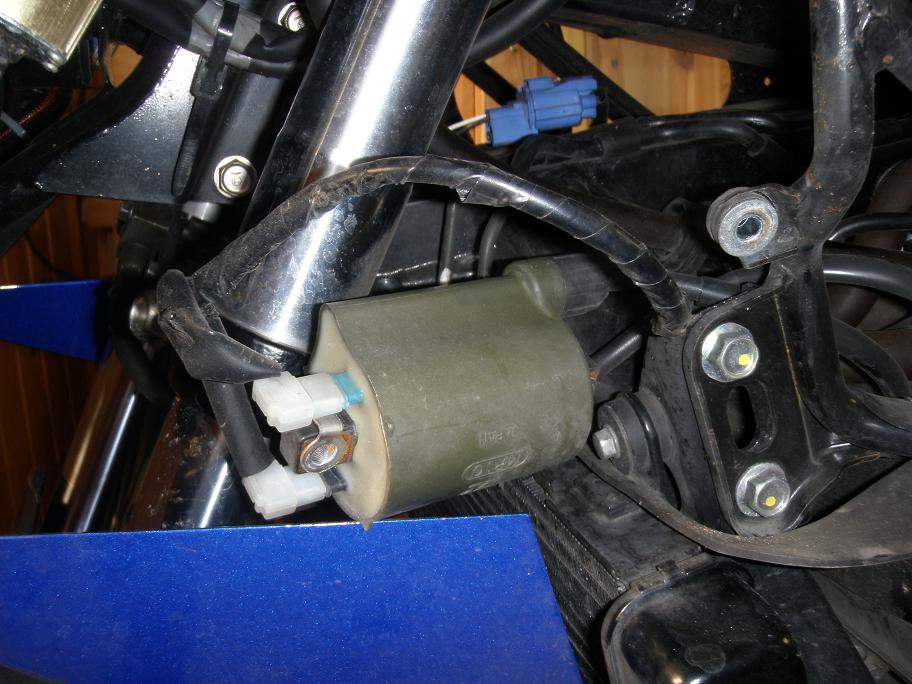
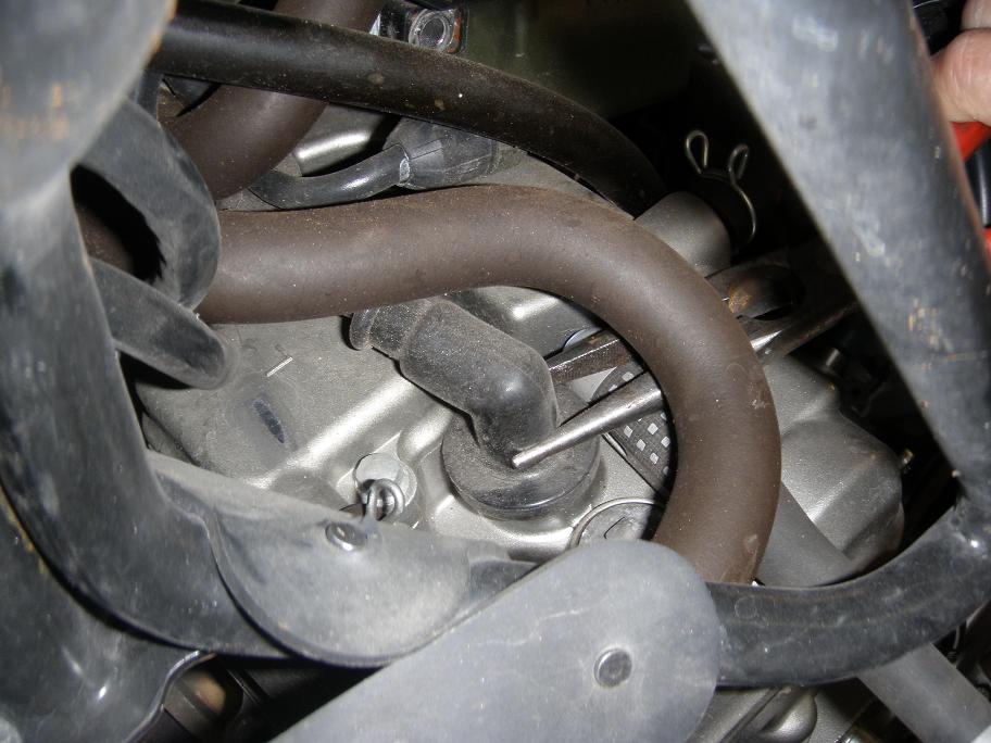
The pictures below show how components are located. Be sure to place all hoses and cables in the
same way when you assemble again.
It is possible to remove the ignition system parts without removing PAIR control valve and PAIR hoses, but it is very triggy to do it without pulling the wires hard or bending them sharply with consequent damage to the ignition system. It is much easier to first to loosen all hose and cable connections, unfasten ignition coils and then - when everything is loose, to remove the components one by one, as cable and hose ends become removeable.
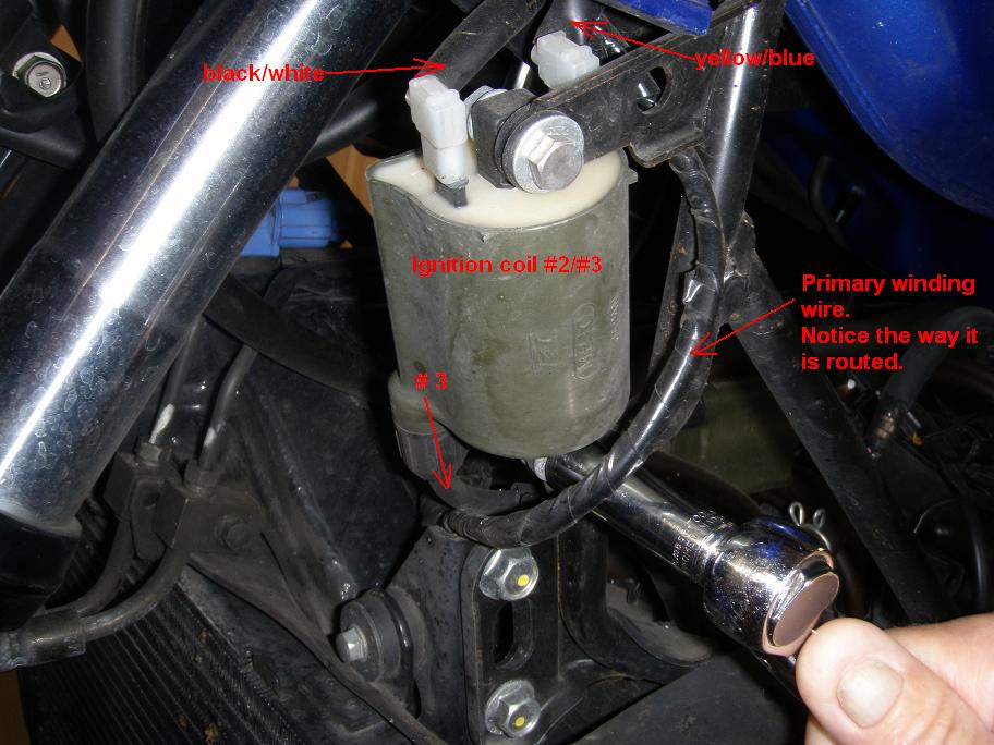
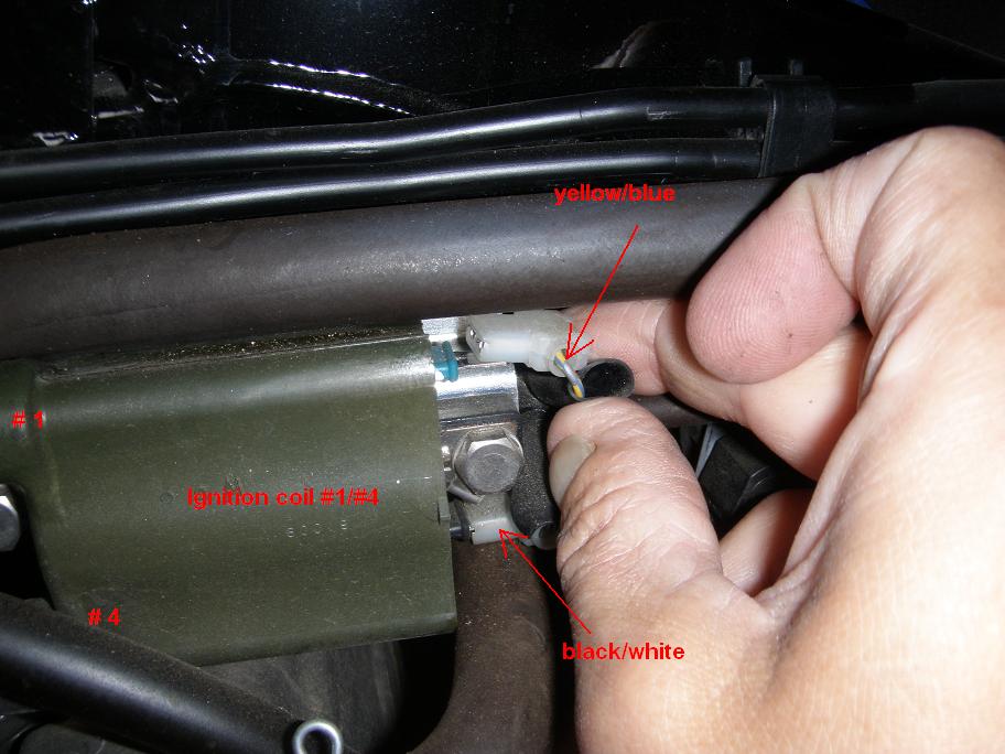
Notice: The cylinders and their respective spark plugs are numbered #1, #2, #3 and #4, where #1 is at the far left side of the bike and #4 is on far right side. The ignition coil mounted in the left cowl support frame is for #2 and #3 spark plugs, and the coil mounted on the left side of the frame (under the tank) is for #1 and #4. Be carefull not to interchange the coils as their cable lengths are not identical.
6.1 Using a tusch-pen, mark the ignition coils with their respective spark plug numbers (as described above), so you do not get this wrong during reassembly.
6.2 Remove the two 28 mm long 6 mm bolts and their nuts holding ignition coil #2/#3 to the
cowl support frame. Just let the coil lie loose while you continue.
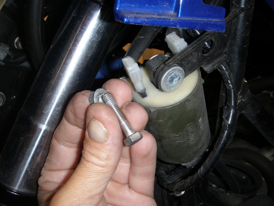
6.3 Disconnect the primary wires on ignition coil #1/#4 and the remove the two 22 mm long
6 mm bolts holding the coil to the mounting bracket on the center frame. Just let the coil
lie loose while you continue.
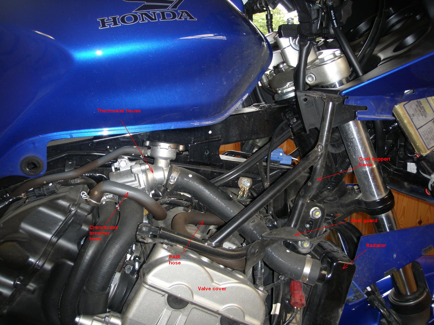
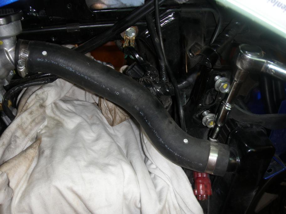
7.0 It is now time to remove the cowl support frames from both sides and a coolant hose in
order to improve access.
These steps are not strictly required, but they make it a lot easier to get your big hands into
the 'battle zone' and to get the valve cover in and out, hence reducing the risc of
damageing components.
You may observe from the pictures that I did these things somewhat later in the process, when I
realized that it would be a great help.
7.1 Unhook the heat guard rubber from the taps on the cowl support frames in both sides
7.2 Unscrew the 2 bolts that hold the cowl support frames in each side of the bike
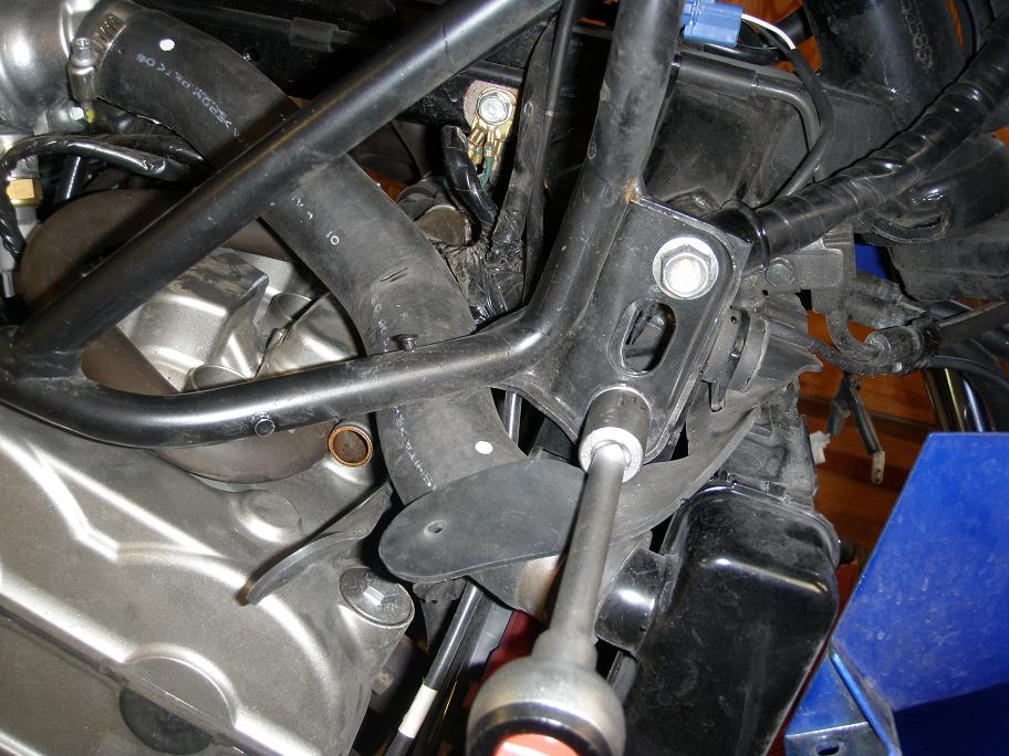
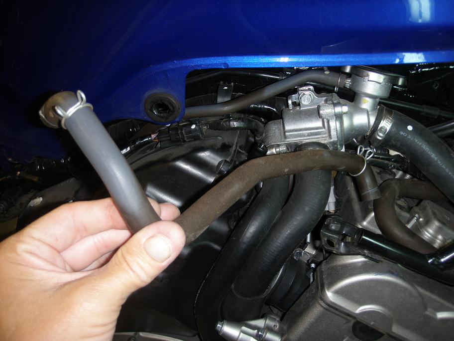
7.3 Remove the coolant hose connecting the thermostat housing with the radiator.
8.0 You are now ready to disconnect PAIR control valve, hoses, ignition coils, spark plug HT-cables and spark plug caps. You may do it in any order you find best.
8.1 Use a pair of pliers and e.g. the handle of a screw driver to release the spark plug caps.
Do not pull in the cables themselves as they may break inside and damage the performance of the
ignition system.
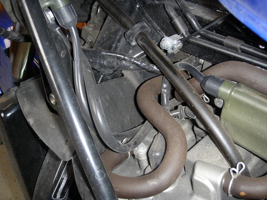
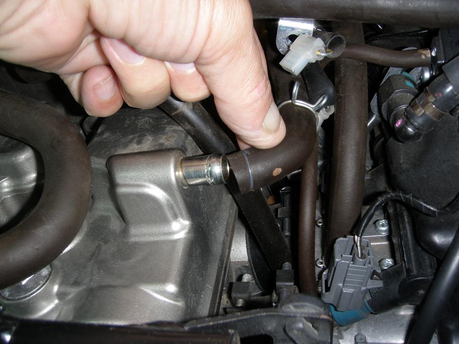
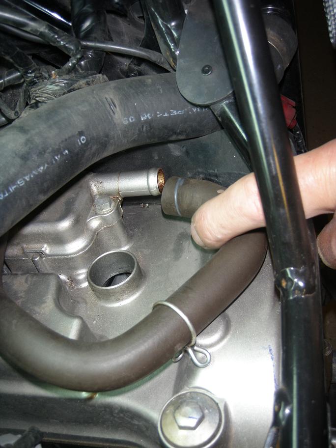
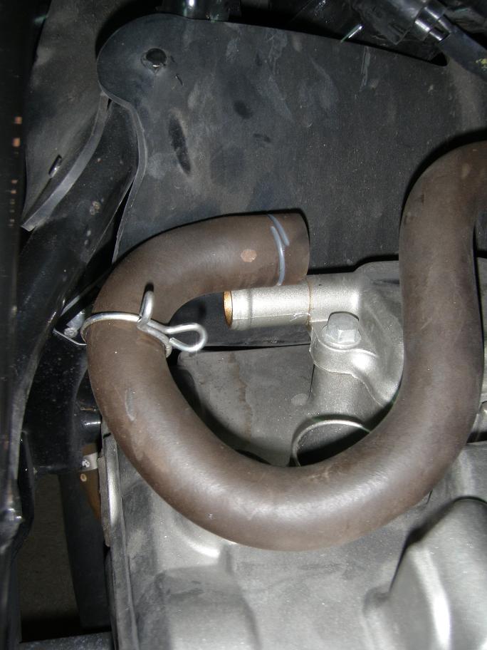
8.2 Disconnect and remove the crankcase breather hose.
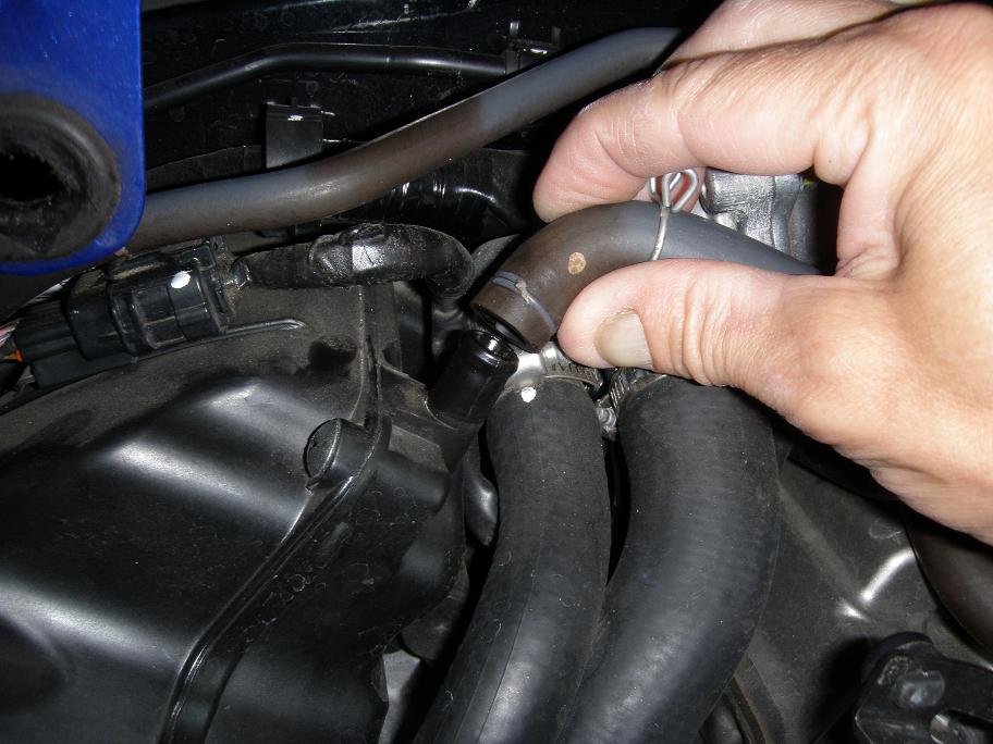
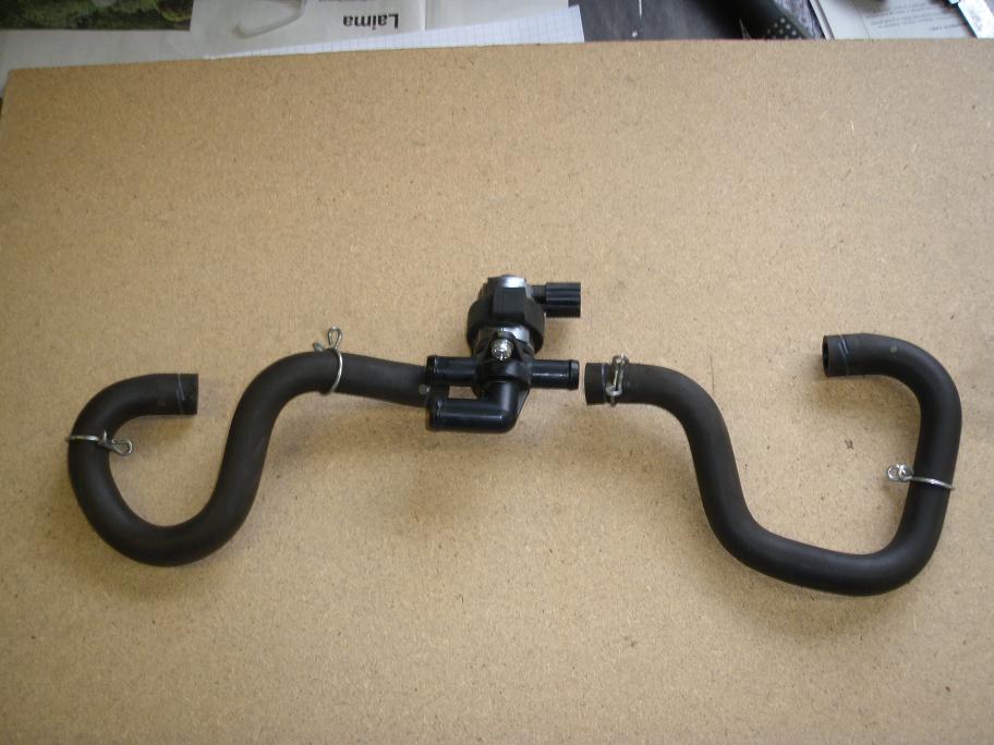
8.2 Disconnect the PAIR hoses from the valve cover and PAIR control valve rubber mount from
tap on frame.
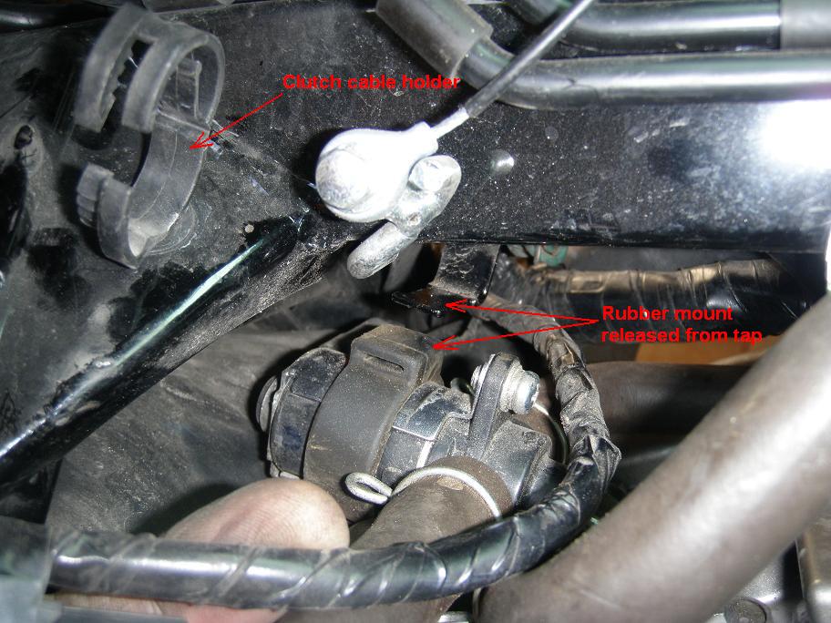
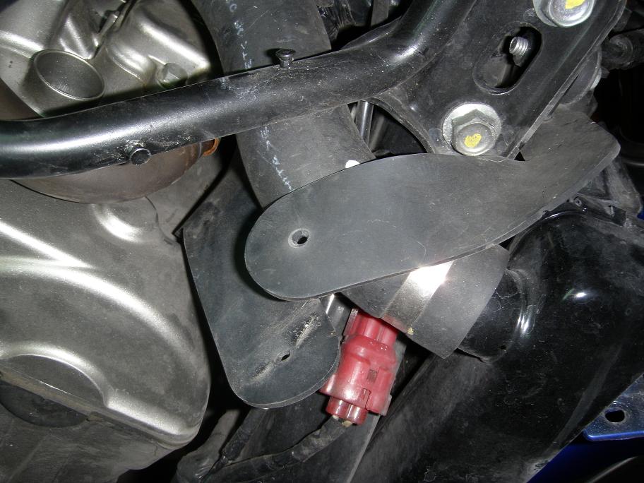
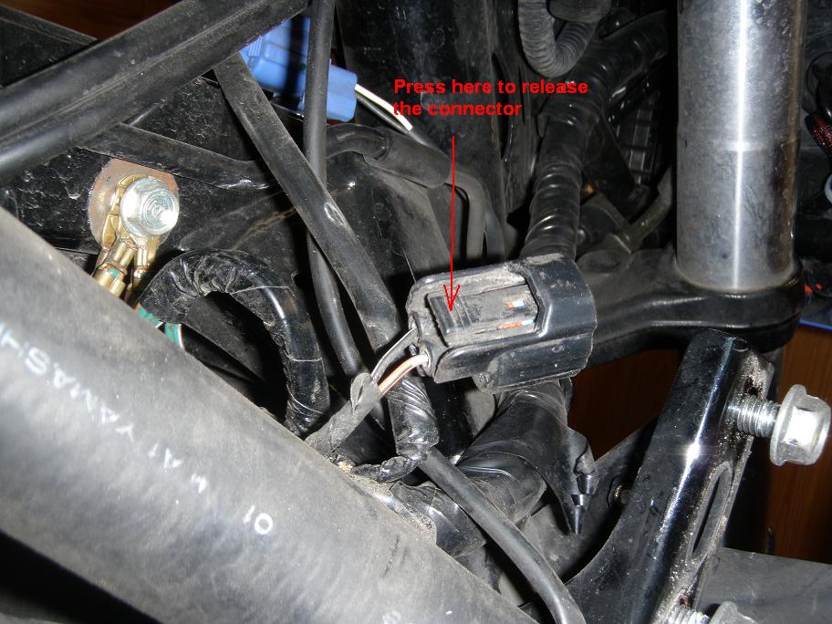
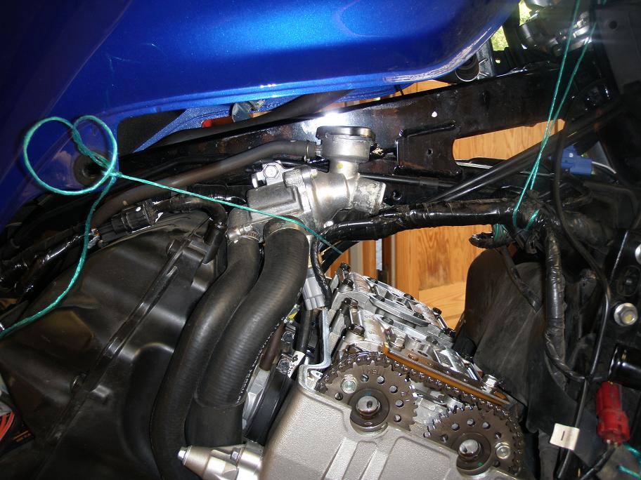
8.3 The PAIR inlet hose comming from the air cleaner can now be disconnected from the PAIR
control valve. You do not need to disconnect it from the air cleaner, just bend it up above
the frame bar and let it rest there. Disconnect the electrical 2-pin connector from the PAIR
control solenoid. It is pretty difficult to get your fingers in there, but you have to press
on the side of the harness connector to get it released. On the center picture below, the
connector has been pulled out to the right side of the engine to get a good look at it.
Normally it's position is under the frame bar.
8.4 Now everything has been released and you can remove the parts in whatever sequence you find best. Again - be sure not to pull hard in any of the spark plug cables.
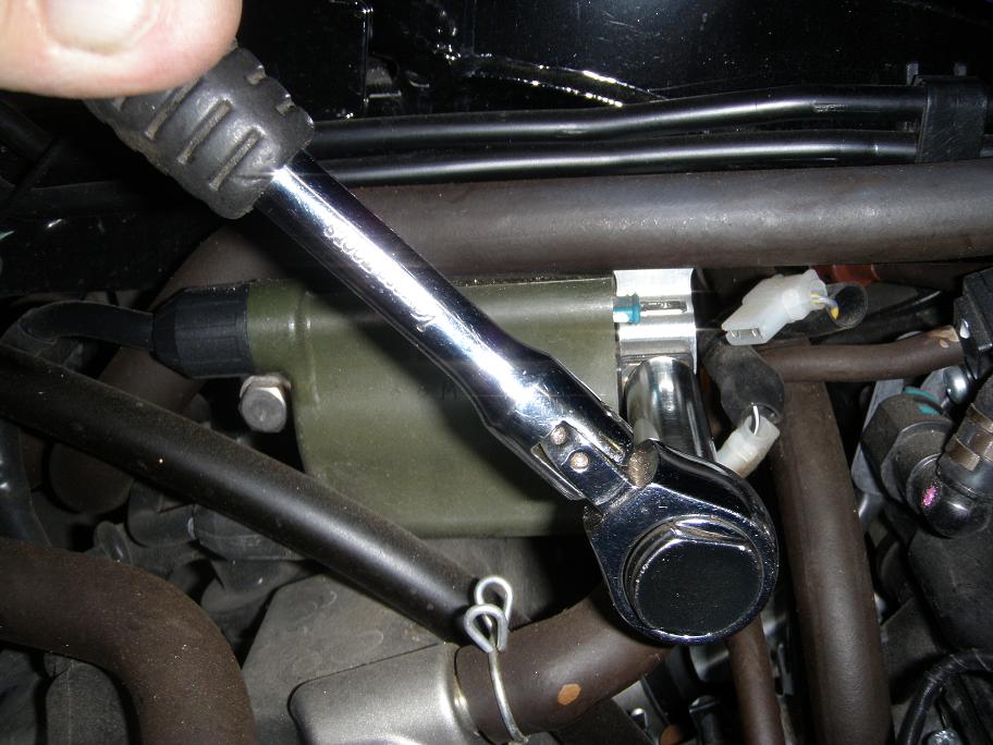
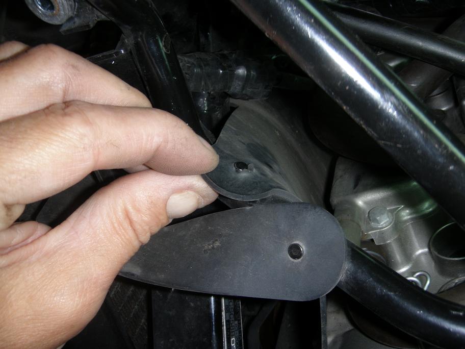
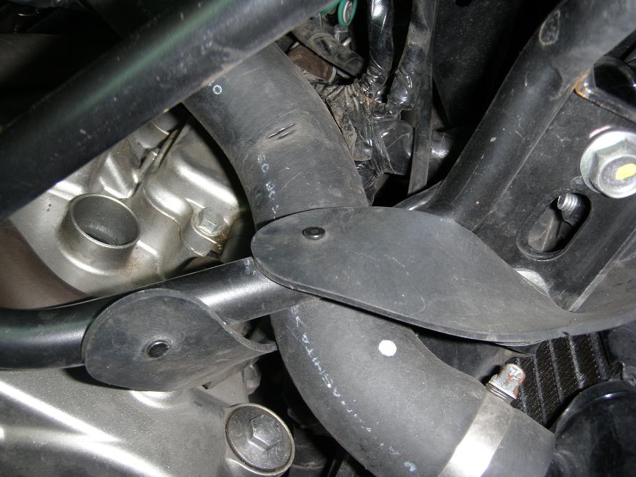
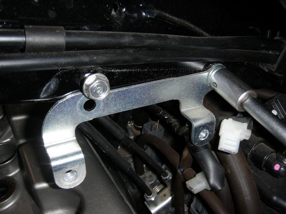
8.5 To further improve access to the valve cover, also remove the mounting bracket for
ignition coil #1/#4.
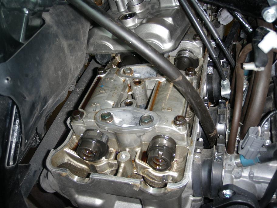
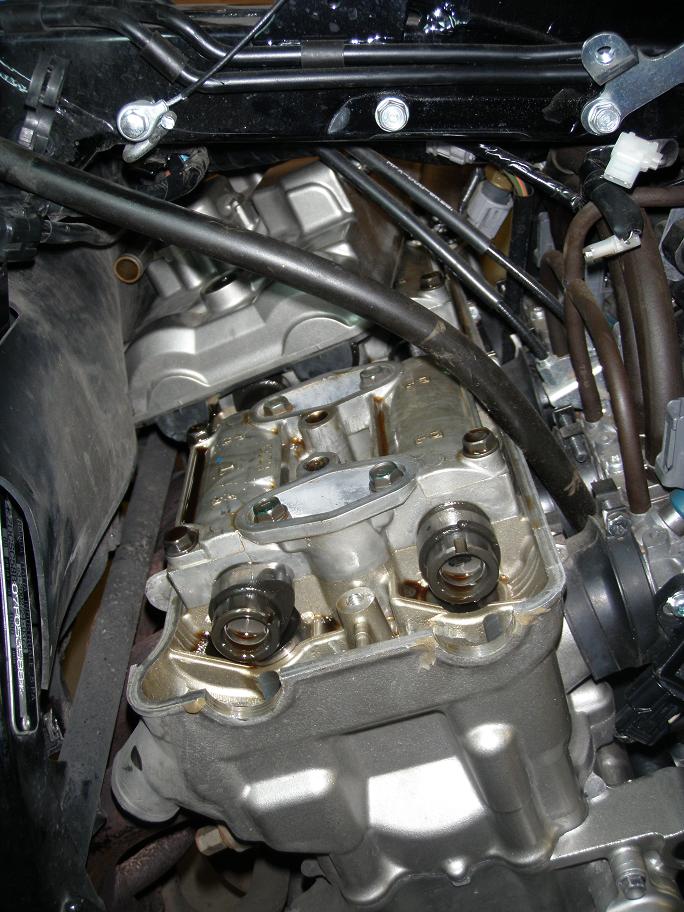
9.0 You have now dismantled enough to remove the valve cover, but before you do this,
everything arround and above the valve cover must be cleaned to ensure that no dirt will fall
into the interior of the engine. Also - if you have access to presurized air, blow out any
dirt that may be lieing in the spark plug holes.
Finally you may tie up some of the cables with a couple of strings. This is shown further below
under step number 13.
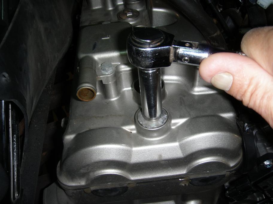
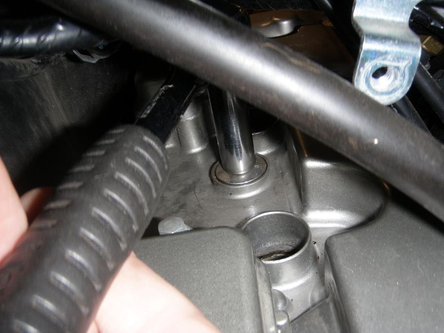
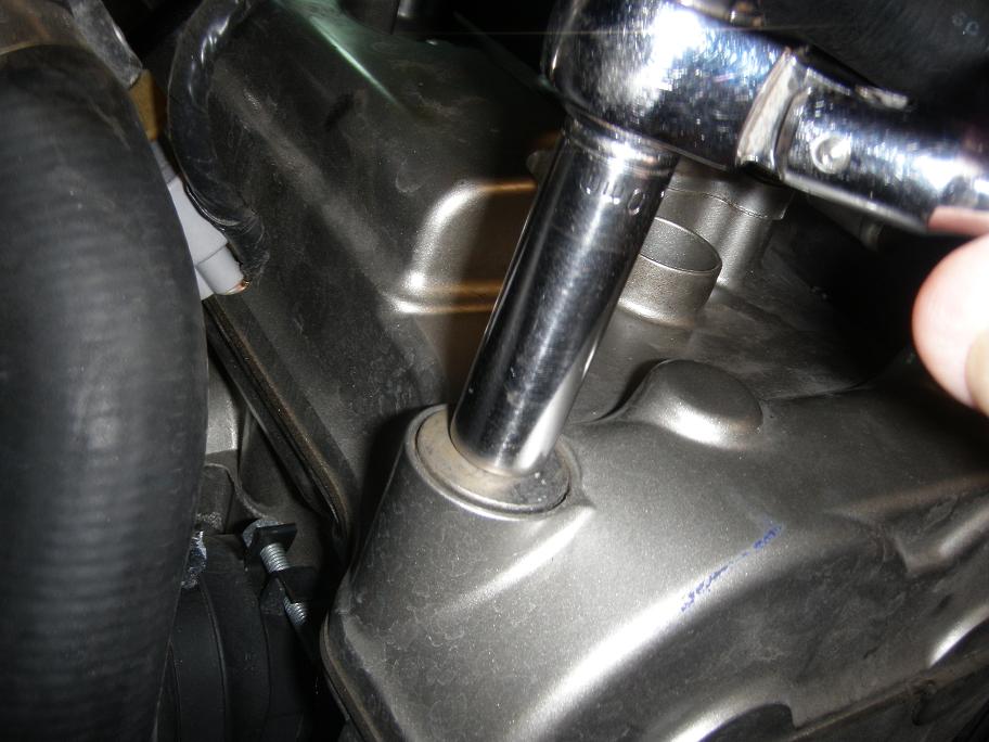
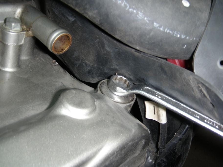
10.0 Loosen each of the 4 valve cover bolts half a turn, then another half turn for each
bolt, and finally remove each bolt.
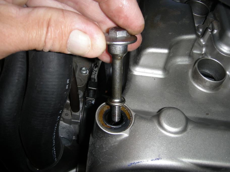
11.0 While applying some lifting force to the rear left corner of the valve cover, tap gently
on the cover side with a plastic hammer to get the gasket to release. Then lift the cover a few
centimeters and ease it out towards the right side of the bike. Be carefull not to damage the
semi-circles on the rubber gasket.
Clean the edges of the cylinder head, taking care to remove all remenicenses of silicone RTV
(Room Temperature Vulcanising) gasket. Be carefull not to make scratches in the aluminum, and
don't drop any of the silicone stuf into the cylinder head.
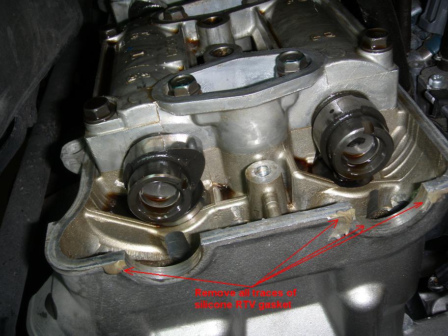
The top of the engine is now ready for valve clearance inspection or other work in this area.
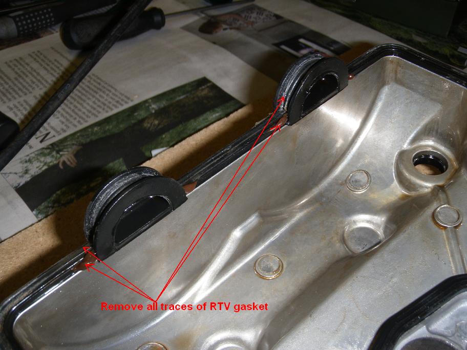
12.0 With the valve cover lieing topside down, remove all traces of silicone RTV gasket
from the rubber gasket. Make sure not to drop any of it down into the valve cover. It should
not be nescesary to remove the gasket from the valve cover, but if there seems to be traces
of RTV gasket on that side, you may want to take the gasket off and clean it. Take your
time to do all this right, or you may not be able to make an oil-tight mount of the valve
cover.
13.0 If you have not already done it under step 9, then tie up some of the cables with a
couple of strings. This will make it easyer to get the valver cover back on the cylinder head.
14.0 Ease the valve cover in over the cylinder head from the right side and let it rest there
while still missing about 20 mm (see the picture below).
Important: The following must be done with correct timing and you will need an assistent.
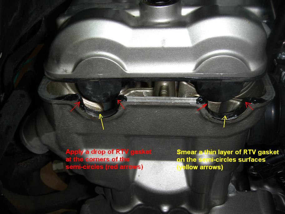
Within two minutes: Smear a thin layer of silicone RTV gasket on the surfaces of the
semi-circles and also apply a drop of silicone RTV gasket on the semi-circle corners at the
left end of the cylinder head. Do the same at the right end of the cylinder head (you will have
to work from the underside of the valve cover for this).
Wait 3-5 minuets to let the surface of the RTV gasket dry a little. Then - with help from your
assistent - lift the valve cover, move it to be alligned correctly with the cylinder head
and then simultaneously lower it down into it's final position. Be sure to do this in one
downwards move. Do not lift it again, because you might risc breaking the RTV seal you just
formed.
Immediately after, insert the 4 valve cover bolts and in a cyclic sequence graduately tighten
them to a torqe of 10 Nm (1 kgm, 7 lbfft). Then gently dry off any excess RTV gasket while it
is still soft.
15.0 The remaining assembly is now just to reverse the dismantling sequence while taking the following into account:
15.1 This is your chance to clean all parts and the engine itself. Smear all hooses, ignition
coils and spark plug cables and caps with a thin layer of silicone oil and dry it off again with
a cloth. The silicone oil will protect rubber surface from cracking, and it will also prevent
moisture build up on ignition system parts, thus preventing false routes for the high voltage
currents.
Notice: While we are on this subject: This is what you should do on your car before every
winter. And don't forget the rubber arround the car doors either!
15.2 Working your way back to step 8 (included), mount all parts into their respective positions, but do not yet connect any hoose ends or spark plug caps.
15.3 Make sure all hoses and cables are routed correctly as shown on the previous pictures.
15.4 Press down the spark plug caps so that they snap correctly into position. You will find that it requires quite som force (you may even need the help of an assistant) to get them down. Make sure you positively hear several clicks from each cap as it slides down over the end of the spark plug.
15.5 Continue with all the remaining reverse steps 7 to 1. When mounting the primary wires on the ignition coils, be sure to connect them as they were before (collors are shown on the large pictures in steps 6.3 and 6.2, click on the pictures to see them). The ignition will work OK even if you invert the connections, but - depending on the internal design of the ignition coils - it may influence radio frequency emmission.
Finished.
© Copyright 2009 FireBladerDk - Last updated 2009-08-23