DID also has a less expencive version, but since I ever started collecting tools, I have always bought the best.
This DIY describes how to replace chain and sprockets on a 2007 CBF1000A Honda motorcycle and is applicable for 2006 to 2010 models. This replacement must be done when the chain has elongated to the specified maximum limit. Depending on driving style, lubrication intervals and road conditions, this may typically be after some 40.000 km (27.000 miles). On my bike it was done at 40.400 km and again at 82.600 km.
This is an easy DIY task, provided you have the right tools for it. It is also a task which for safety reasons much be carried out with care. You don't want the new chain to break while driving fast on the highway! A first timer may spend 5 hours or more doing it, an experienced might do it in 1 hour.
Tools, spareparts and consumables needed:

When doing DIY work you will undoubdtedly at some point run into troubles like e.g. stuck bolts or other things which will not come apart. Instead of just spinning out of control using the big hammer, have a look here: " Undoing Stuck Bolts, Nuts and other Metal Parts".
This summary presents the short version of what to do:
Detailed descriptions for each step are given in the following sections.
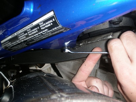
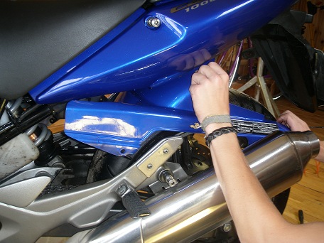
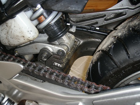
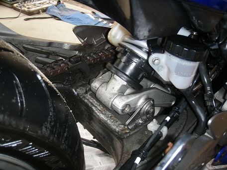
1.0 Remove the hugger to get easy access to the chain.
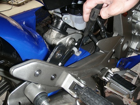
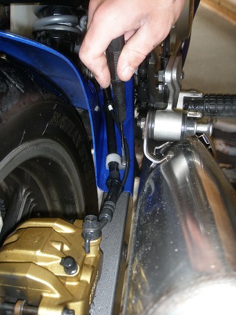
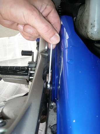
2.0 Remove the gear linkage:
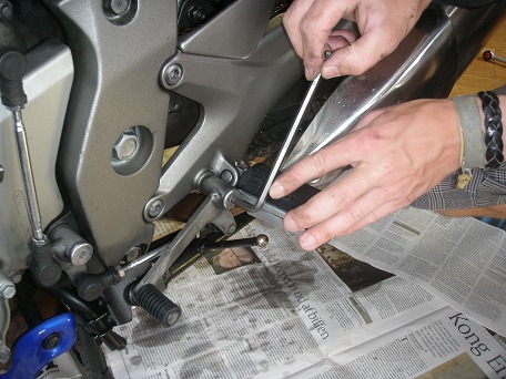
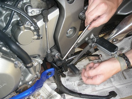
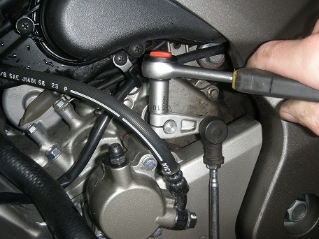
Unscrew the two lower bolts and remove the pinch bolt at the gear shift arm (above right).
Pull the gear shift arm of the splines (below left). Notice the angle when you pull it off,
so you can hit the same angle on reassembly (if you prefer, you really only need to unmount
the gear shift arm and let it hang down).
3.0 Remove the hydralic clutch slave cylinder:
First place a "do not touch" label on the clutch handle.
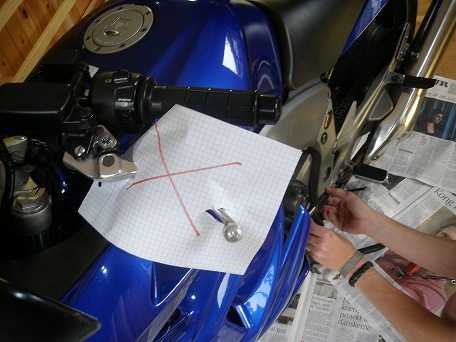
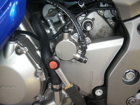
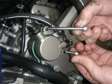
Then loosen and remove the two long and one short bolts holding the hydralic clutch slave cylinder.
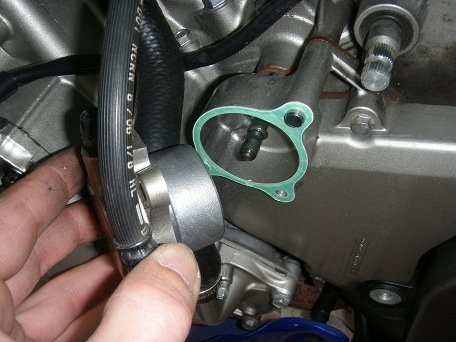
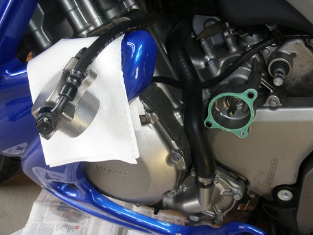
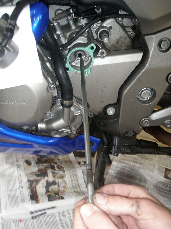
Pull the clutch slave cylinder away and let it hang to the left. Be carefull not to damage the gasket. Pull out the long clutch lifter rod.
4.0 Remove the front sprocket cover and guide plate:
This cover is also referred to as the left cranckcase rear cover. It is
mounted with a socalled guide plate behind it, and is fixed into position by
two dowel pins and two bolts. First unscrew the two bolts holding the cover.
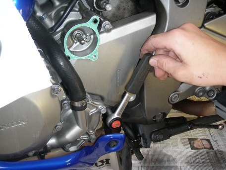
The cover is easy to get loose, but it may be a little difficult to get it past the
rubber tube on the cooling water pump. The trick is to wriggle the guide plate off
the dowel pins and away. Then there will be sufficient clearance to get the cover
off.
5.0 Remove the front sprocket bolt:
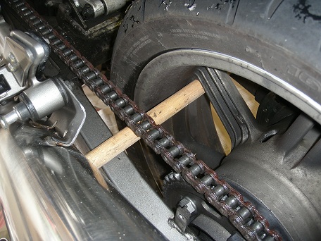
Place a 33 cm long wood stick through the rear wheel to prevent forward rotation
(below left).
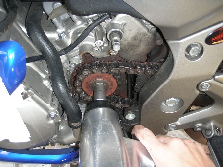
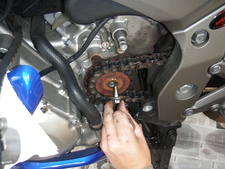
Remove the bolt holding the 16 teeth front sprocket. You must use a six edged 14 mm
top for this as the bolt will otherwise be damaged due to the high torque required
to loosen it. If you do not have a pressurized air tool, you may likely have to use a
hammer on your socket wrench to loosen the bolt.
6.0 Break the chain:
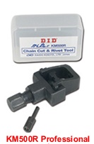
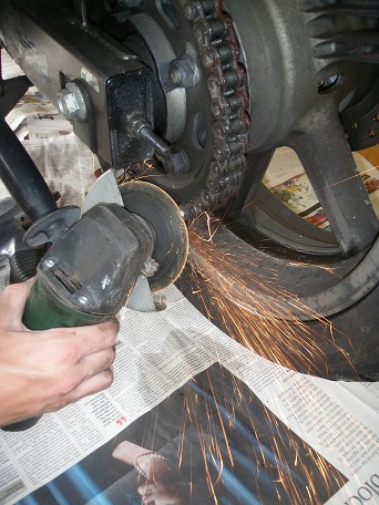
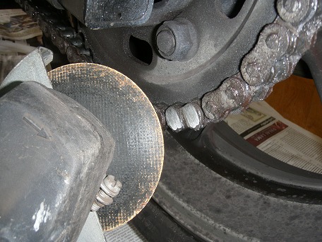
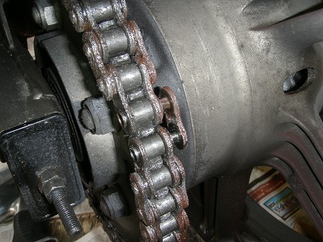
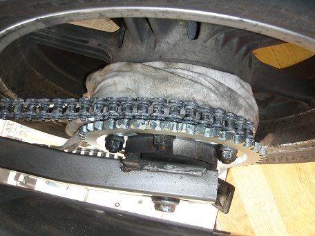
I had no experience with KM500R DID Chain Cut & Rivet Tool so I decided to use
an angle grinder to grind down two rivet heads on a randomly chosen link as shown in
the images (below left). It only took a couple of minutes. Then the chain could be
removed.
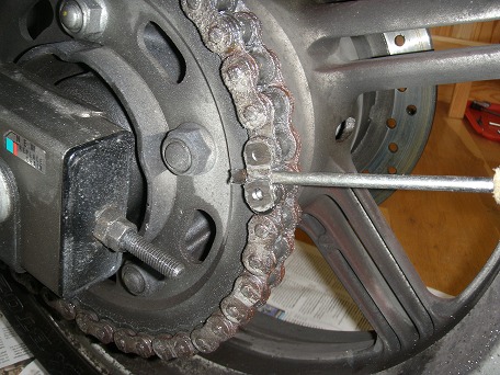
The connecting link plate is then removed with a screwdriver which is tapped lightly
on the end with a hammer (third image from left above). Finally the connecting link
is simply pushed out and the entire chain can be removed.
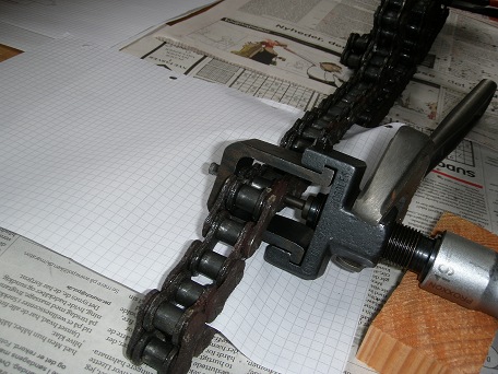
Later I broke the chain again with the KM500R DID Chain Cut & Rivet Tool
as you can see in the following description and pictures. I found this to be much easyer
than I first expected, so next time I will use this method.
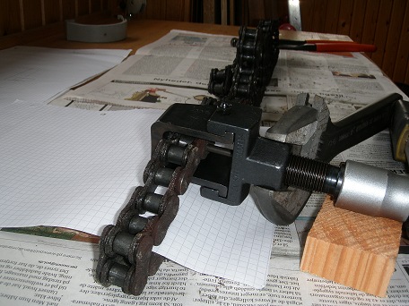
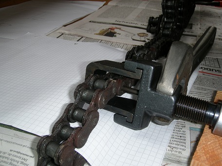
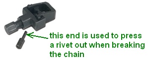
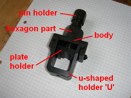
The cutting and rivetting pin is set into the pin holder with the long thin riveting pin
pointing out.
The u-shaped holder 'U' is moved in over the chain from one side, and the u-shaped holder
is slided sideways into position A which is marked on the side of the u-shaped holder.
In this position a small hole in the bottom of the U will be alligned with the riveting
pin so the rivet can pass out through this hole.
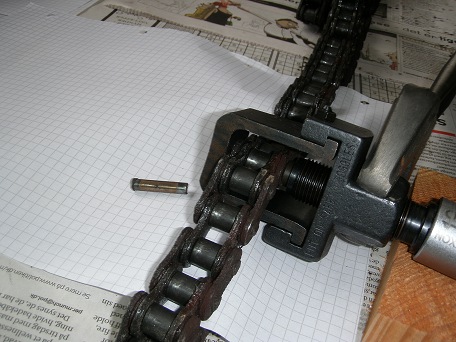
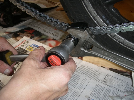
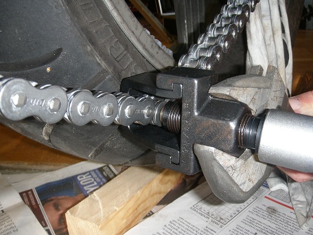
The riveting pin is positioned on the center of a randomly selected rivet head and
pressure is applied by turning the 19 mm bolt, while holding contra on the 28 mm hexagon
part of the tool (below left).
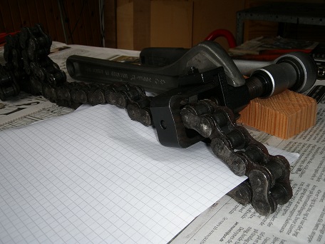
Continue turning until the pin is pressed completely out of the chain. Remove
the tool and you're finished.
7.0 Remove the Rear Wheel and Sprocket:
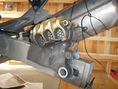
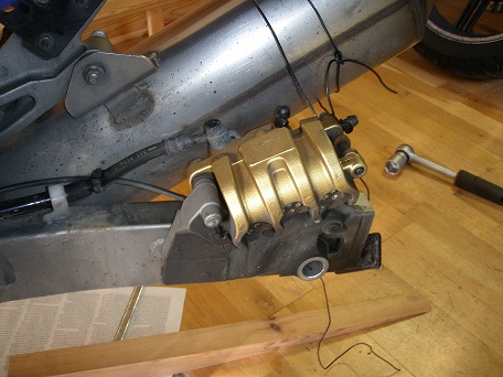
Push the rear brake caliper a little back to achieve a gap as shown below (see
more details in the Rear Brakepads Replacement article). If hand
force is not enough, use a helper or a pair of pliers as shown on the middle image
below.
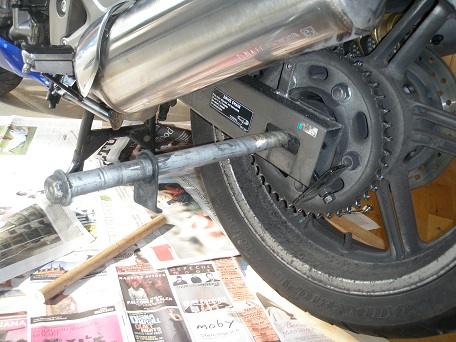
Tie up the rear brake caliper to the exhaust (below, second picture from left). Then
remove the rear axle nut on the right side of the bike and pull out the rear axle from
the left side (below left). Remove the rear wheel. There is just enough space to get
it out. When you do this, it may happen that the front end of a brake pad is displaced
sideways and dropps down so the pad is hanging down from the pad pin. Should this
happen, simply remove the pad pin and the brake pads completely and remount them when
the wheel has been remounted. See the Rear Brakepads
Replacement article for further details on this.
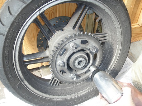
Finally remove the 43 teeth rear sprocket (below right) by undoing the 5 nuts.
OBS: Be carefull not to drop the rear sprocket unit out of the rear wheel hub. It can
fall out if you turn the weel on its side with the sprocket down.
8.0 Inspection and cleaning:
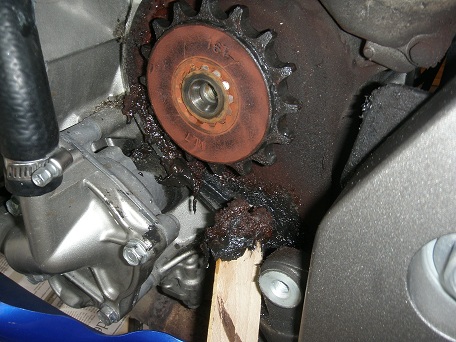
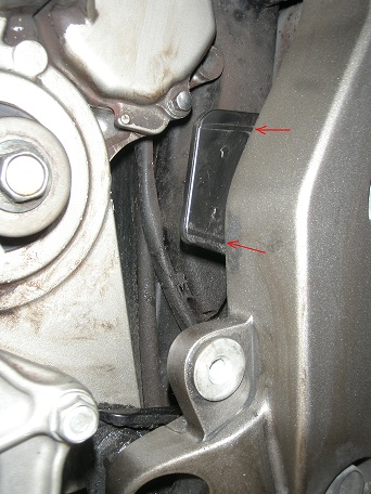
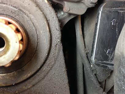
Using e.g. a thin piece of wood, clean out old chain oil from the area around the
front sprocket and drive chain slider. Check that the drive chain slider has not been
worn too much down (image below middle at 40.400 km and right at 82.600 km). If it has
been worn to either of the wear indicators, the slider must be replaced.
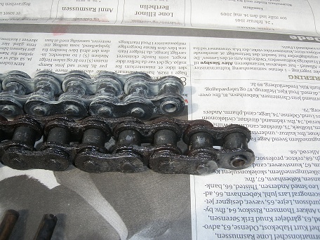
Check that the new chain has the same number of links as the old one. Standard for
this bike is 120 links with sprockets having 16 teeth at font and 43 teeth at rear.
Notice that 120 links is the same as having 120 pins in total.
9.0 Mount the Rear Sprocket:
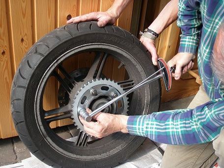
Clean the threads and nuts for the rear sprocket and smear the threads with copper
grease. Mount the new rear sprocket with the number of teeth visible and tighten the
nuts in a criss-cross pattern to a torque which according to the Honda Shop Manual
should be 108 Nm (11.0 kgfm, 80 lbfft). This figure is dry torque so having smeared
with copper grease the torque should be decreased a little to say 90 Nm.
The German repair handbook for CBF1000 from Bucheli Verlag AG however recommends
further reduction to 70 Nm, as some Honda specialists claims there is a risc of pulling
the mounting studs out of the hub.
Whichever torque you decide to use, you should keep an eye on the nuts during the
follwing period to ensure they do not get loose. Best is to put a dot of paint on
the edge of each nut, so you can check that this 'seal' is not broken.
10.0 Mount the Rear Wheel:
Mount the rear wheel, but do not tighten the rear axle bolt yet.
11.0 Mount the Front Sprocket:
Mount the Front Sprocket, but do not tighten the sprocket bolt yet. That will have to
wait untill the chain is on.
12.0 Mount and Rivet the new Chain:
Feed the chain around the front sprocket and place it over the rear sprocket. Make
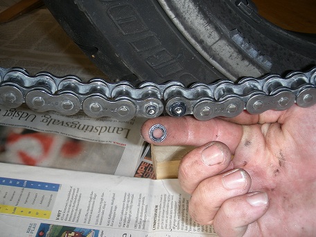
sure there is a well greased O-ring on each pin on the connection link. Assemble
the chain with the connecting link inserted from the inside out.
Place two O-rings on the other side of the chain and ensure they are well greased
(image below middle).
Reference: DID's Chain
Installation and Maintenance Instructions.
Press the connection link plate onto the pins with fingerforce. You will only
be able to press the connection plate enough to hold it into position, the rest will
now be pressed in with the riveting tool:
Place the u-shaped holder 'U' arround the chain and slide the body onto
the holder. Place the plate holder in the tool between the pin holder
and the connection plate. The image above right shows the correct configuration of
the tool for this operation.
Allign the tool so it is centralized on the connection plate and tighten the pin
holder untill you feel the tourge increases sharply, indicating that the connection
plate has reached the correct position (image below left).
Now remove the plate holder from the tool and slide the u-shaped holder sideways into position B which is marked on the side of the u-shaped holder.
Centralize the riveting point over one of the pins on the connection link and
tighten by hand untill the riveting point is in firm contact with the hole in the end
of the pin (image below middle). When you tighten the pin holder by hand it is
important that you can really feel that the riveting point centralizes itself in the
hole. This will ensure that the rivet is not made out of center.
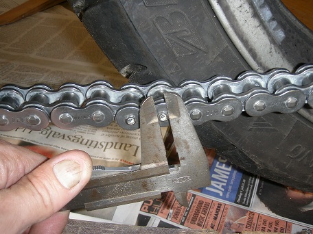
Using spanners - turn the pin holder a few degrees while holding contra on the
tool body. You will feel the tourge rising sharply. Remove the tool and measure the
diameter of the rivet as shown on the right image below.
Repeat the above last two steps untill the rivet diameter meassures between 5.5 to 5.8 mm (0.217" to 0.228"). If you mount a chain from a different manufacturer, then be sure to follow the manufacturers specifications.
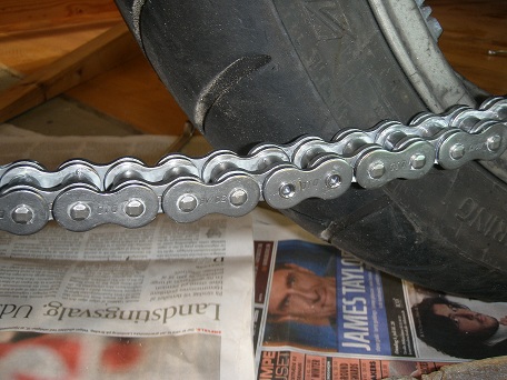
The finalized rivets must look like the ones shown on the above image. They must
be symmetrically rivetted to the correct diameter and not have any cracks.
13.0 Tighten the Front Sprocket: Do not forget this!
Place the 33 cm long wood stick through the rear wheel again, this time to prevent
rearwards rotation and tighten the front sprocket bolt to 54 Nm (5.5 kgfm, 40 lbfft).
14.0 Mount the front Sprocket cover and guide plate
If you removed the hugger, this shall also be remounted. It may be difficult to mount the front bolt for the hugger due to very little space, so you may want to undo the nut fixating the rear end of the exhaust and loosen the two Allen bolts holding the left footpeg bracket so it can swing a little out. The Allen bolts must be re-tightened with 27 Nm (2.8 kgfm, 20 lbfft).
15.0 Mount the Clutch Lifter Rod and Hydralic Clutch Slave Cylinder:
You may smear the rod with a thin layer of silicone grease.
16.0 Mount Gear Linkage:
Be sure to place it in the correct angle.
17.0 Adjust the Chain:
Tighten the large chain adjustment nuts exactly the same number of turns on
both sides, untill the chain slack is close to 40 mm. Then, referring to the
Chain Maintenance article, adjust the chain slack to
approximately 25 mm, and remember to check that the left and right sides are adjusted
identically, i.e. that the markings on each side are identically aligned.
Measure and write down how wide the hole behind the rear axle nut is. On the image below, this gap is 11.0 mm, so when the gap has reduced by 5 mm (the width of the green band) to 6.0 mm, it will be time for yet another chain replacement.
Tip: Whenever possible, leave bolts, nuts and screws in their original positions while you continue work. Then you have them in the right place for reassembly.
Tip: Remember to smear the threads on bolts and screws with copper grease before you remount them. Then you will have an easy task, next time you have to disassemble.
The thread Chain Replacement DIY on www.cbf1000.com may be used for comments and feed back, or you may mail directly to me (mail addres is on the front page).
See also:
Chain Replacement post by pharis on www.cbf1000.com .
Finished.
� Copyright 2011 FireBladerDk - 2011-08-27 - last updated 2022-02-12